


New function for AutoCAD: ModPlus ISO

New to AutoCAD! But try carefully!
Here under this slogan comes a new function. And why? Read under the cut
Finally, six months later, after a huge number of attempts and finding a solution, I completed this unique function! This is not even a function - it is a plugin in the plugin, which will also be developed further. The first version comes out with just one sub-function, since it is necessary to run it through. Well, enough to torment - we meet the function «ModPlus ISO»!
So what is this beast? When you open Configurator, then you will see everything as it should be - a new function, which you can also connect to AutoCAD:
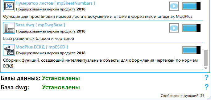
But if you go to the Adaptation tab, you will not see there the possibility to add a Function in the menu. Inquisitive users may have noticed that some time ago, when updating the Configurator, an adaptation tab appeared on the adaptation tab, that if the Function is not in the list, then it builds the tab on the ribbon itself. So this was done just for «ModPlus ISO».
Good. Launch AutoCAD and see a new tab on the ribbon:
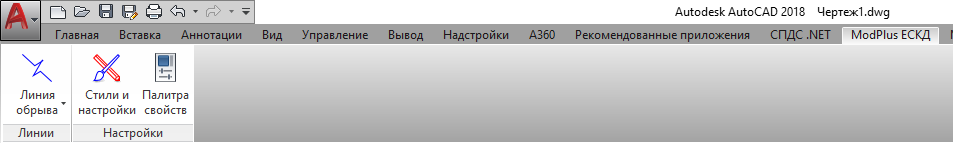
At the moment there are three buttons - one sub-function and two general-purpose buttons. And to explain what so special in «ModPlus ISO» i want to remind you about such a thing as proxy objects (they are also Custom Entities) - these are intelligent entities written in ObjectARX. And their most important problem is known to everyone - in the absence of the necessary software, you get a drawing with a bunch of non-editable entities. And sometimes they also can not be deleted.
So here «ModPlus ISO» - this is an attempt to create such intelligent entities, but without using ObjectARX. All entities (well, so far it is one) are based on anonymous blocks. Opening the drawing without the ModPlus plugin you will receive the usual anonymous blocks, which then you can also blow up and do what you want with the received entities (lines, polylines, etc.)
Let's try - open the "ModPlus ISO" tab and click on the button «Break line». In the list that opens, we see that there are three buttons. However, all three types of entity - this is one entity! Unclear? We start the function "Break line" and then everything is standard - we indicate two points and we get a break line. The resulting clipping line has handles for which you can change it again later. And now we open the properties and the entity and see ... the properties of the ordinary block. Not comme il faut)) Therefore we return to the tape in the "ModPlus ISO" tab and see the button there «Properties palette». Click and you will open a new palette. Select the created entity again and see its extended properties:
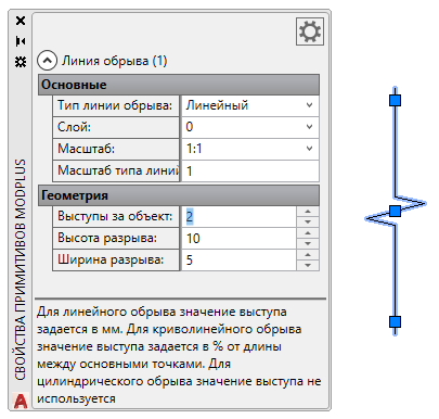
Let's talk about them a little bit:
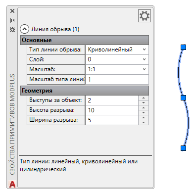
Break line type – now we have "Linear" there. If we select another type from the list, our entity will change its appearance. Go back to the ribbon and launch other options for the break line - and now everything becomes clear - different buttons create a entity with a different type. But you can always change it in the properties palette:
Layer – corresponds to the same property in the usual properties palette. It would seem that this is an extra point, but when I tell you about the styles below, everything will fall into place.
Scale – sets the scale of the entity. Values are given as an annotation scale in the drawing. But, my entities are not annotative - I decided that this is unnecessary. Yes, and in terms of implementation - just hell ))
Line type scale – sets the line type scale for entities (for example, for a polyline) inside a block. This was done on purpose, since it is impossible to change this property in blocks.
I will not describe other properties here - you will find all the hints in the properties palette and in the style settings window.
By the way, the developers of the plug-in Autodesk SPDS.Net 2018 have done exactly the same implementation of properties. But faster than me ))
Now about the properties and settings of the plugin. Again, go to the ribbon and click the button «Styles and settings». In the tab «Styles editor» the three main fields are a list of categories that correspond to subfunctions. Now only one item - the line of the cliff. When you expand the category, you will receive a list of styles. Above the three buttons - create, delete and make the default. When you select the system style in the list, you will not be able to edit it, so we will create a new style and look at the result:
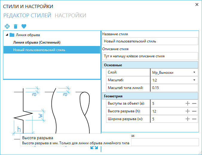
Below we have a field with a picture. It would seem that everything is just like everyone else - just a picture, which shows what the object has. But I will not be me if I do not add flavor to my project. This is not just a picture - it is part of the window. The color scheme of the picture changes depending on the settings for the theme for the plugin. And that is not unimportant - when you hover the mouse over an element of the picture, you will see a hint with a description of the property!
On the right there will be a field for setting properties that can change with the style, as well as the name of the style and description (optional). This is where it becomes clear why there is a "Layer" property. You can set a certain layer for the style, specify the style as the default style and then all created entities will be created on this layer. "And now - do I have to create the necessary layers every time?" You thought now. And no! The plugin remembers all the settings of the selected layer and can create the desired layer in the new drawing. And all this you can control by setting. Let's look at them and see:
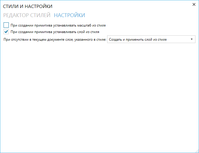
When you hover the mouse, a hint will pop up, but I will tell you again and again about the item “When creating a entity, set the scale from the style”. In fact, everything is simple - if this check box is not present, then when creating a entity, it will be set to the current scale of drawing annotations. But if you tick the box, the scale will be set from the style, regardless of the annotative scale of the drawing. With layers is also quite clear - if you ticked, then the layer will be put the one that is registered in style. And an additional item will appear - what to do if there is no layer. Put the option "create and apply" and then in the drawing will create a layer of style, when creating a entity.
I hope that these settings will be quite flexible. So far there are few points, but I think there will be more - at least entities with text are still expected.
Well, now about the most important thing - about caution.
The fact is that almost no one has done such experiments before me. I say “practically” because there was one plugin with similar technology, but for the distant 2012 version of AutoCAD, the author is the one that never answered me. The aforementioned Autodesk SPDS.Net 2018 was created using a similar technique, but they are based not on blocks, but on ordinary entities. So, when developing, I sooooo much caught fatal errors. Now the version is of course fairly stable and I don’t catch fatal errors at all, but I haven’t tested the Function on real projects in real work. I very much hope for the responsiveness of users of the ModPlus plugin, and at the same time I urge you to be careful and carefully test the new Function. There are still possible conditions under which something will go wrong, but I physically cannot predict them now. Although AutoCAD can catch fatal errors without any plugins. =))
There is still a lot of work ahead with this function, but the foundation is solid. There are also many ideas - the implementation of such common and well-known entities like Axis, Welding Designation, Tags, etc., and new interesting ideas. Which I will not disclose yet.
Well, I think that's all. I look forward to your feedback, comments, ideas! And as usual - enjoy your work with the ModPlus plugin!