Analysis, grouping and reinforcement of beams for specified conditions
Icon
Related news and articles
Using
Plugin allows you to process both individually selected beams and all beams in a view or in a document. Transverse reinforcement can be assembled using a variety of rebar shape options. Plugin can work even on an empty template.
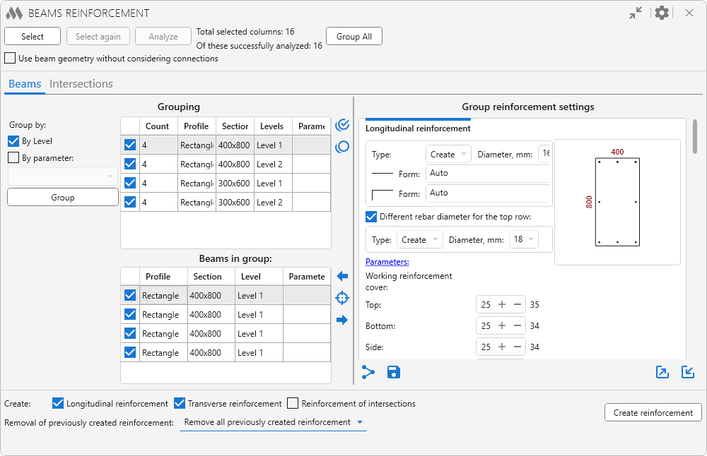
The main plugin window is divided into three zones:selection and analysis, reinforcement settings and final settings and starting the reinforcement process.
There are options in the window title:
.png) – collapse window contents
– collapse window contents
.png) – general plugin settings:
– general plugin settings:
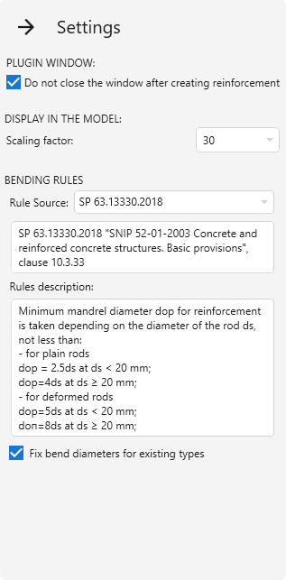
Scaling factor – scale selection option for the command Display in model the beam selected in the list (described below).
In the group Bending rules the source of rules for rebar bending is selected: SP 63.13330.2018 or EN 1992-1-1. Below is the description of rules from the selected norms.
If the option Fix bend diameters for existing types is enabled and appropriate types of rebars are found during operation, their bend diameters will be checked and corrected according to the selected standards. When creating new types of rebars, in the case no suitable ones are found, the diameters are always checked and set.
Work with the plugin starts with selecting the beams to be reinforced. To do this, click the button Select and then choose one of the options in the drop-down window: Pick beams, Select all beams on current view or Select all beams in document.
Only beams of rectangular cross-section that have a profile are included in the selection filtering. Also, the beam family property "Material for Model Behavior" must have the values "Concrete" or "Precast concrete".The number of selected beams is displayed at the top of the plugin window.
The button Select again allows you to reselect the beams that were processed in the current view when using the plugin.
Next you need to start the analysis of geometric and parametric data of selected beams using the button Analyze. The number of successfully analyzed beams is displayed in the upper part of the plugin window. The button Group All allows you to group beams and intersections according to the current grouping settings.
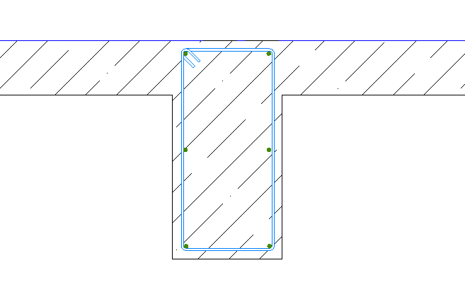
The option Use beam geometry without considering connections allows only the geometry of the beams to be taken into account in the reinforcement in case of transverse connection of beams with other structures (e.g. slabs). If the option is enabled/disabled, the analysis and next grouping of elements must be performed again. Example of reinforcement with the option disabled:
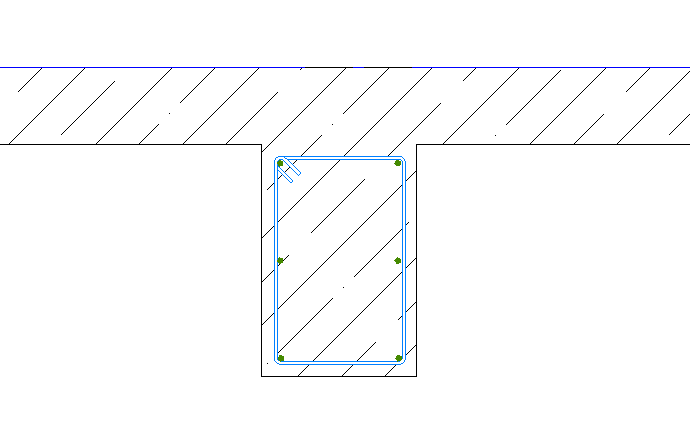
when the option is enabled:
The middle zone of the plugin window includes two tabs for specifying reinforcement settings for beams and their intersections:
Beam reinforcement
Intersection reinforcement
On each tab, tables filled with successfully analyzed and grouped elements are located on the left side of the plugin window, while the right side contains the corresponding reinforcement settings.
There are buttons at the bottom right of each tab:
.png) – allows you to copy the reinforcement settings of the current tab to the checked groups.
– allows you to copy the reinforcement settings of the current tab to the checked groups.
 – allows to save the current reinforcement settings as default reinforcement settings.
 – allows to export current reinforcement settings to an xml file or save them to the reinforcement settings storage.
To save the settings to an xml file, simply click Save to file, the name of the settings can be entered in the opened explorer window.
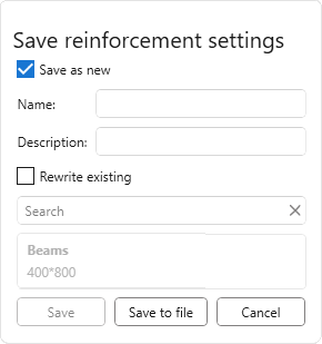
To save the current settings to the storage you should choose one of two saving options:
- Save as new – to save the current settings you need to set Name and Description (optional) of the settings.
- Rewrite existing – current settings will be saved with the name of previously saved settings selected from the list.
Next, to save the settings to the storage you should click Save.
 – allows you to load reinforcement settings from previously exported xml file of reinforcement settings or from the reinforcement settings storage.
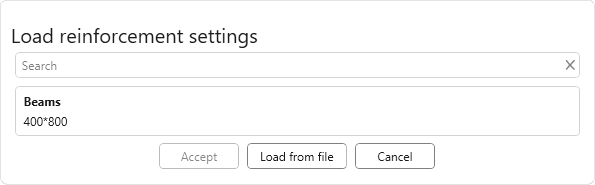
To load the settings from the xml-file you should click Load from file. To load settings from the storage it is necessary to select the required setting in the list and click Accept.
In the row Create: you can specify what type of reinforcement will be created for checked items: Longitudinal reinforcement, Transverse reinforcement, Reinforcement of intersections.
Removal of previously created reinforcement – this option allows you to remove the reinforcement created by the plugin (reinforcement of the same type that is created or all previously created reinforcement), if you want to recreate it.
Create reinforcement – start creating reinforcement of checked categories for beams and intersections.
BEAM REINFORCEMENT
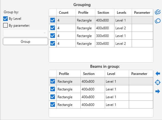
All beams are necessarily grouped by cross-section size. Additionally, elements can be grouped By Level and/or By Parameter selected from the drop-down list using the Group on the left side of the plugin window.
Two tables are placed in the grouping zone. The top is filled with groups of beams. For each group, a flag is checked by default in the list, meaning that for this group of beams, reinforcement is required. To the right of the list are buttons to check all groups in the list  and to uncheck all groups in the list
  .
.
The bottom list is filled with the beams of the group selected in the top table. For each beam a flag is set by default to indicate that reinforcement is required for that beam.
The buttons to the right of the list can be used to display in the model the beam selected in the list  , as well as to display in the model the previous beam in the list
 and the next beam in the list
  , respectively.
Settings are set for a single group of beams, selected in the list of groups in the left part of the plugin window. In the right part of each group of settings there is a field for previewing the beam section according to the current settings.
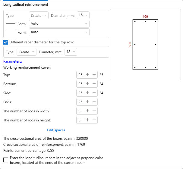
Longitudinal reinforcement
In all groups of reinforcement settings it is possible to specify the shape of rebars for the respective bar types.
For the top row of longitudinal reinforcement, a different type and diameter of reinforcement can be specified by enabling the corresponding option.
In this group the longitudinal reinforcement settings are set: rebar bar type, working reinforcement cover, number of rods in width and height.
To set values of text parameters for the created reinforcement there is a button Parameters, clicking on which opens a dialog box. The list of parameters is filled with the current document:
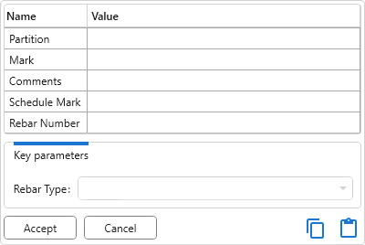
If the current document contains rebars with key parameters, a corresponding section will appear at the bottom of the dialog box, allowing you to select key parameter values from a dropdown list.
When you put the mouse cursor over the preview field, the distances between the faces of the rods are displayed. If you click on the button Edit spaces, a dialog box opens in which you can specify the required spaces both between the edges of the rods (left column) and between the centers of the rods (right column) for each direction:

If the values of diameter,cover or number of rods are changed, the distances between the rods will be reset to equivalent values.
In the plugin window cross-sectional area of the beam, cross-sectional area of reinforcement, reinforcement percentage and binding of working rebar to the edge of the beam by the center of the rebar automatically calculates.
Longitudinal reinforcement joints
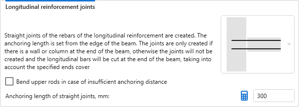
In this group of settings it is possible to select in the drop-down list whether longitudinal reinforcement joints will be created.
The joints are only created if there is a wall or column at the end of the beam, otherwise the joints will not be created and the longitudinal bars will be cut at the end of the beam, taking into account the specified ends cover.
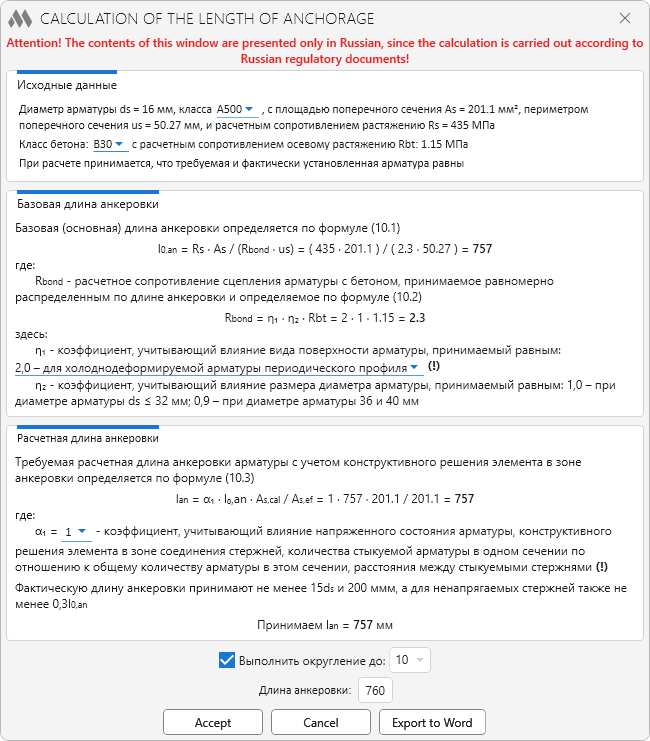
Anchoring length of straight joints can be calculated by pressing  – a window will open with calculation of the length of the anchoring according to SP 52-101-2003:
If there is insufficient anchoring distance, an option can be included to allow the upper rods to be bent.
Transverse reinforcement (layout)
For transverse reinforcement of beams, the layout scheme and forms of transverse reinforcement are configured in separate groups.
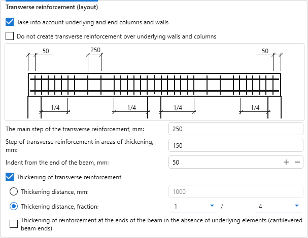
In the settings of the layout scheme it is necessary to set the main step of transverse reinforcement and step of transverse reinforcement in areas of thickening, as well as the indent fromthe beginning of the section. Depending on the settings, the start of the transverse reinforcement section can be the end of a beam or the face of an underlying column/wall.
If the option Thickening of transverse reinforcement is enabled, thickening zones are created at the ends of the beam, their length - Thickening distance, can be set as an absolute value (in mm) or as a fraction of the beam span length.
If the option Take into account underlying and end columns and walls is enabled, transverse reinforcement densification is created only at the points where beams rest on walls or columns and its distance is set from the faces of columns and walls. The following options become available:
- Do not create transverse reinforcement over underlying walls and columns
- option to add thickening of reinforcement at the ends of the beam in the absence of underlying elements (cantilevered beam ends).
Transverse reinforcement (shapes)
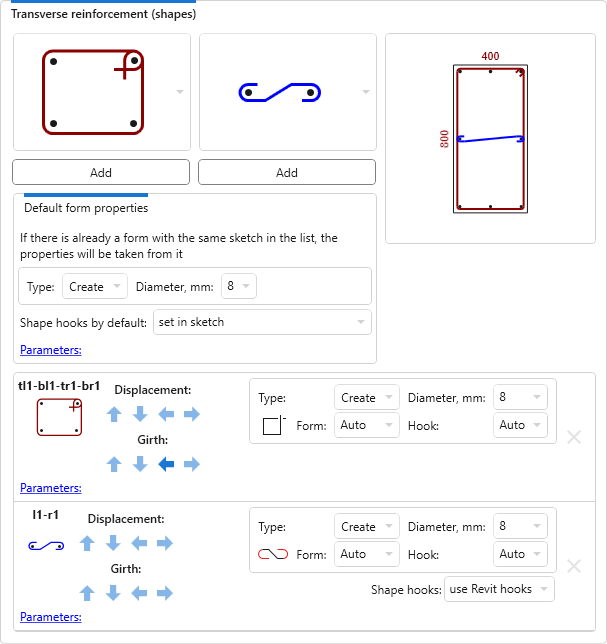
The layout of transverse reinforcement is performed using a defined list of shapes. The list of shapes changes depending on the number of longitudinal reinforcement rods. For some shapes you can change the hook type – use Revit hook or create a hook as part of the sketch.
In the settings group there are two drop-down lists of shapes – for horizontal and vertical layout. Under the lists you can specify the hook type, parameters, diameter and rebar bar type that will be set as defaults for the added transverse reinforcement shapes. After selecting a form in the list, you should click the button Add.
Added forms of transverse reinforcement appear in the preview field of the column section and in the list of added forms.
For each of the added shapes in the list you can specify the form, change parameters, diameter and rebar bar type, as well as hook type, if possible. Shapes can be shifted, change the girth of bars, as well as removed using the corresponding buttons next to each item in the list.
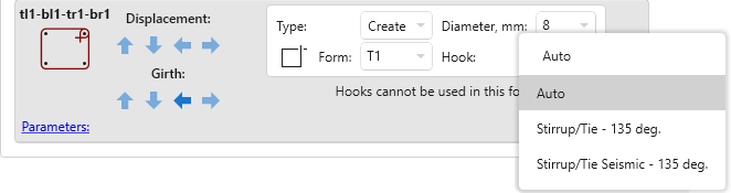
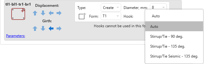
For shapes with hooks, you can additionally select the hook type from the Hook drop-down list. The list of hook types available for selection will depend on the settings of General Reinforcement Settings of the current document.
The "Include hooks in Rebar Shape definition" option can only be changed before the first rebar is created in the current document.
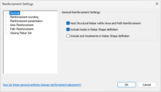
If the "Include hooks in Rebar Shape definition" option is enabled, only hook types with an angle suitable for the selected shape are included in the list of hooks.
If the above option is disabled, the list of hooks will include all types of hooks available for the selected shape.
INTERSECTION REINFORCEMENT
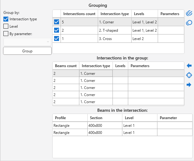
Intersections can be grouped by Intersection type, Level, and By parameter of beams selected from the drop-down list using the Group button on the left side of the plugin window.
Three tables are placed in the grouping zone. The top is filled with groups of intersections. For each group, a flag is checked by default in the list, meaning that for this group of intersections, reinforcement is required.
The middle list is filled with the intersections of the group selected in the top table.
The buttons to the right of the top and middle tables work similarly to the Beams tab buttons.
The bottom table shows the beams included in the intersection selected in the middle table.
The settings are set for a separate group of intersections selected in the list of groups in the left part of the plugin window.
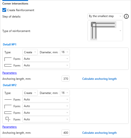
Settings for corner intersections:
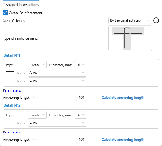
Settings for T-shaped intersections:
Settings for cross intersections:
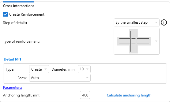
The required Type of reinforcement is selected from the drop-down list. Depending on the selected reinforcement type, the parameters, type, diameter and form of the rebar for one or two details must be set, and the Anchoring length must be calculated. When you move the cursor over the settings for Detail №1 or Detail №2, the corresponding rebar is highlighted in the Type of reinforcement scheme.


